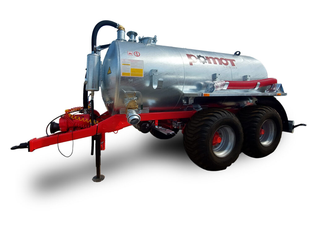
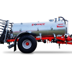
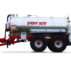
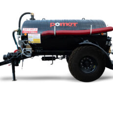
Standard Equipment
-
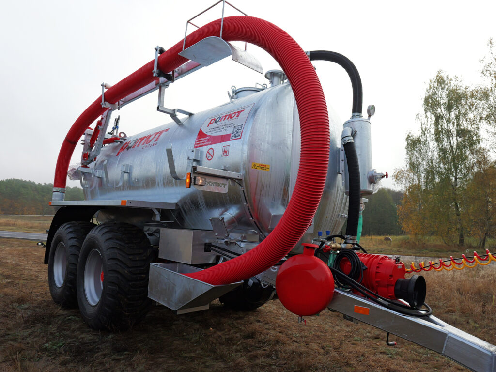
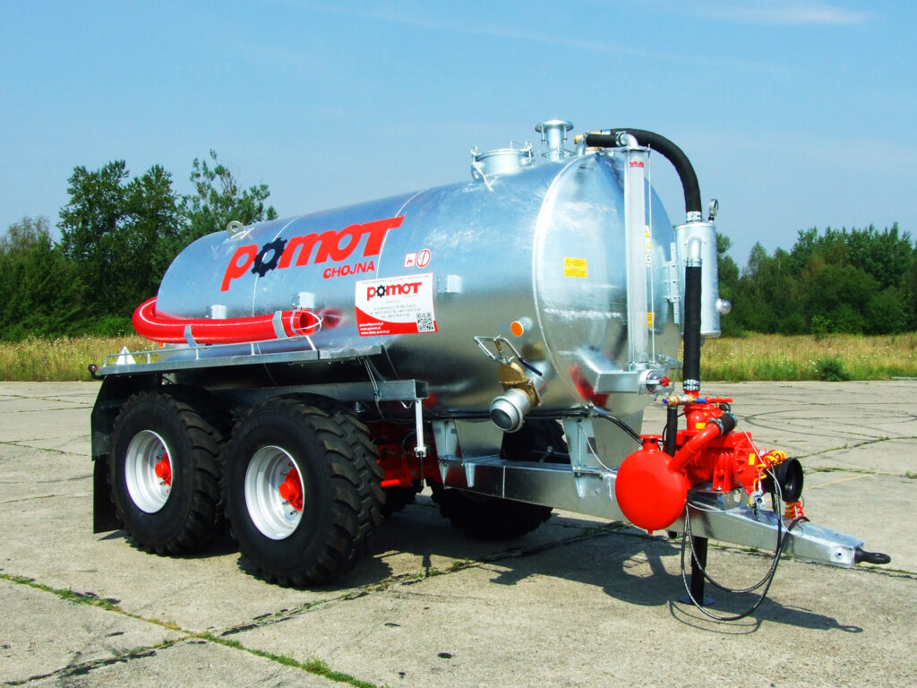
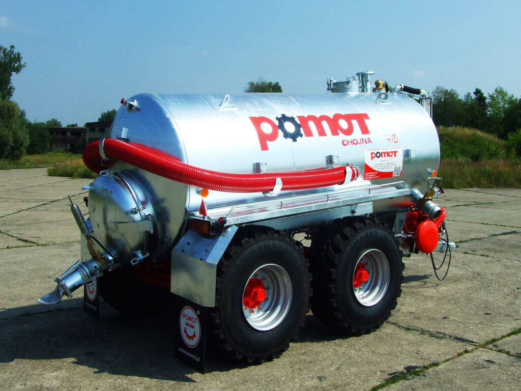
Tank
-
Tank hot-dip galvanized on both sides
-
Tank passivation protecting fresh zinc from slurry corrosion
-
Rear manhole ø700 mm – hinged cover
-
Tubular level indicator with sight glass
-
Drain outlet with 1½″ valve – located at the lowest point of the tank
-
4″ sight glass on the rear tank head
-
Top manhole ø350 mm
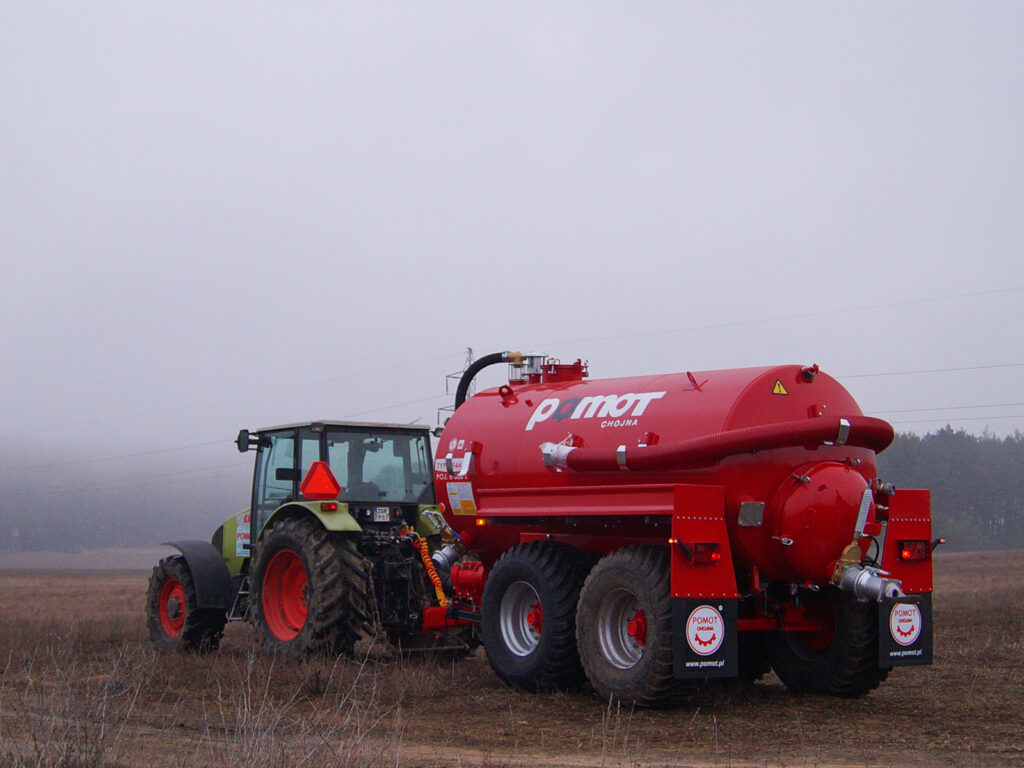
Tank Construction: Self-supporting or frame-mounted
-
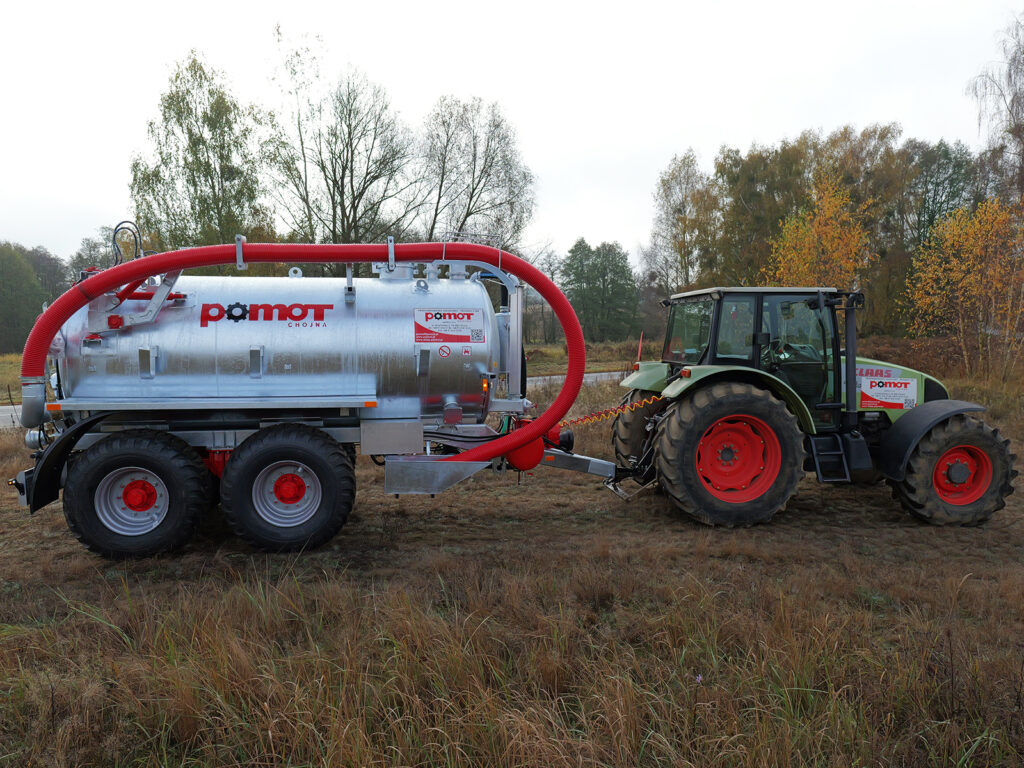
SELF-SUPPORTING – drawbar mounted on reinforced supports under the tank, hot-dip galvanized
-
FRAME – tank mounted on a frame made of closed-section profiles
-
Interchangeable hitch – bolted ø50 mm
-
Mechanically adjustable support leg
-
Single axle or tandem axle with leaf spring suspension
-
Tires according to the table
-
Mudguards
-
Two-line pneumatic brake system with 4-stage brake force adjustment
-
Hand-operated parking brake
-
Compressor – type according to the table
-
Drive 540 rpm or 1000 rpm (on request)
-
Reinforced heat-resistant hoses connecting fittings
-
Overflow protection with double-ball valve and sight glass on top of the tank, plus a siphon with sight glass
-
Vacuum-pressure gauge
-
Two safety valves: overpressure up to 0.05 MPa and vacuum up to -0.05 MPa
-
Oil separator – wet air filter, silencer reducing compressor noise
Suction Outlets
-
6″ suction inlets ø150 mm
-
Main drain outlet on rear manhole cover 6″ with 6″ hydraulic slide valve
-
Front left and right: blanked off, prepared for manual slide valve installation
-
Rear outlet: blanked off, prepared for manual slide valve installation
Electrical & Lighting
-
12V electrical and lighting installation
-
6″ (ø150 mm) hose
-
Transport holders for suction hose
-
Suction hose with strainer basket preventing large objects from being sucked in
-
Suction hose length: 6 meters
Spreading Device
-
Profiled spreading plate POMOT 94 pattern, spreading width up to 14 m
Type Approval
-
Certificate enabling registration and operation on public roads
Power Take-Off Shaft
SPECIFICATION TABLE
VERSION SUSPENSION TIRE DIMENSIONS TIRES COMPRESSOR TYPE SELF-SUPPORTING CONSTRUCTION ECONOMIC 2 spring axles 1080×390 400 R 22.5 MEC or KD 6500 STANDARD 2 spring axles 1180×510 500/60-22.5 MEC or KD 6500 CLASIC 2 spring axles 1180×510 500/60-22.5 MEC or KD 8000 PREMIUM 2 spring axles 1235×550 550/60×22.5 MEC or KD 8000 FRAME CONSTRUCTION ECONOMIC 2 spring axles 1080×390 400 R 22.5 MEC or KD 6500 STANDARD 2 spring axles 1180×510 500/60-22.5 MEC or KD 6500 CLASIC 2 spring axles 1180×510 500/60-22.5 MEC or KD 8000 PREMIUM 2 spring axles 1235×550 550/60×22.5 MEC or KD 8000 -